
Training 3: Reading checks, steps and clauses
A calculation is only as useful as your check of it. This chapter reads one that fails.
Set it up. New steel beam, mark B-1: W16X31, A992, 30 ft simple span, D = 0.5 kip/ft, L = 0.7 kip/ft, self-weight on, compression flange braced at a spacing of 10 ft, LRFD, deflection limits span / 360 and span / 240.
The status bar #
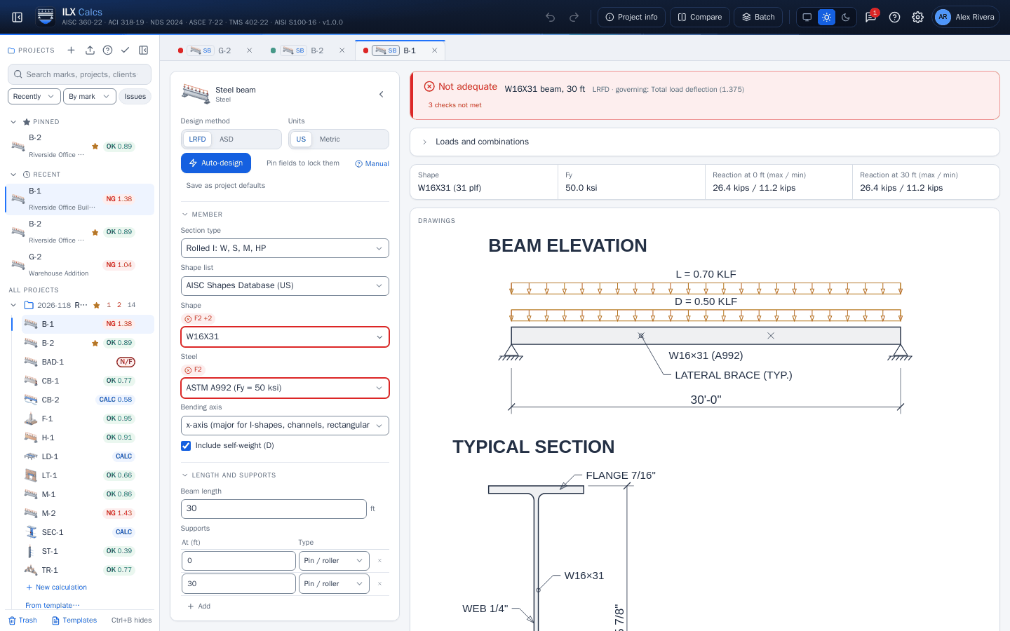
The bar reads Not adequate, W16X31 beam, 30 ft, governing Total load deflection (1.375), 3 checks not met. The inputs that matter to a failing check carry a red mark with the clause, here F2 on the shape and the steel.
There are three states, and tools have a fourth:
- Adequate: every check is met.
- Not adequate: at least one is not. The results are still calculated, so you can see by how much.
- Not feasible: the inputs describe something that cannot be calculated, and there are no results to trust. See below.
- Calculated: a tool with no pass or fail, such as the load takeoff or the section builder.
The checks table #
Below the drawings, All checks lists every check. Each row gives the required value, the available value, the ratio and the load combination that governs it.
| Check | Clause | Required | Available | Ratio | Governs |
|---|---|---|---|---|---|
| Flexural strength | AISC 360-22 F2 | 197.7 kip-ft | 144.5 kip-ft | 1.368 | 1.2D + 1.6L |
| Live load deflection | IBC 2021 Table 1604.3 (limit entered) | 1.173 in | 1 in | 1.173 | L |
| Total load deflection | IBC 2021 Table 1604.3 (limit entered) | 2.063 in | 1.5 in | 1.375 | D + L |
The buttons above the table show All, Failed or Strength only. Code compliance, the next tab, lists the limits and recommendations that are not strength checks. A clause marked (to confirm against the code text) is one this version has not yet confirmed against the code text; read that clause yourself.
Open a check: the steps #
Select a row. Every equation appears with its values, its result and its clause:
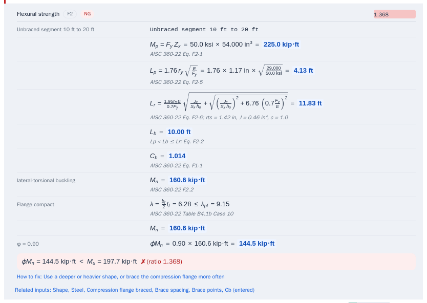
Read them as you would a hand calculation. Here, in the governing segment Unbraced segment 10 ft to 20 ft:
| Step | Result | Clause |
|---|---|---|
| Mp = Fy Zx | 225.0 kip-ft | AISC 360-22 Eq. F2-1 |
| Lp = 1.76 ry √(E/Fy) | 4.13 ft | Eq. F2-5 |
| Lr | 11.83 ft | Eq. F2-6 |
| Lb, between Lp and Lr | 10.00 ft | Eq. F2-2 applies |
| Cb | 1.014 | Eq. F1-1 |
| Mn | 160.6 kip-ft | F2.2 |
| φMn = 0.90 × 160.6 | 144.5 kip-ft |
The end of the steps states the comparison, gives How to fix (here: Use a deeper or heavier shape, or brace the compression flange more often) and links the Related inputs. Show inputs takes you to them.
Loads and combinations #
Open Loads and combinations above the results. It lists what was evaluated. Enter service loads, each with its type (D, L, Lr, S, R, W, E): the program applies the ASCE 7-22 combinations of those types and reports the governing one per check. Self-weight is added to D when selected, which is why the moment above is 197.7 kip-ft and not the 193.5 kip-ft of the entered loads alone (1.72 kip/ft on 30 ft). See Loads and combinations for what is and is not modeled.
Not feasible #
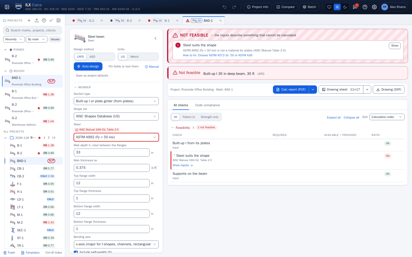
Here a plate girder was left on A992, which AISC Manual Table 2-5 does not list for plates. The banner names the problem, its reference and the fix; Show takes you to the input. Choose ASTM A572 Gr. 50 or ASTM A36 and the calculation runs.
What the ratio does not tell you #
A ratio under 1.00 means the checks this type performs are met for the inputs you gave. It says nothing about checks the type does not perform. Read each chapter's Limitations, and see Limits and your responsibility.
Next: The Wizard and auto-design.